
Transport 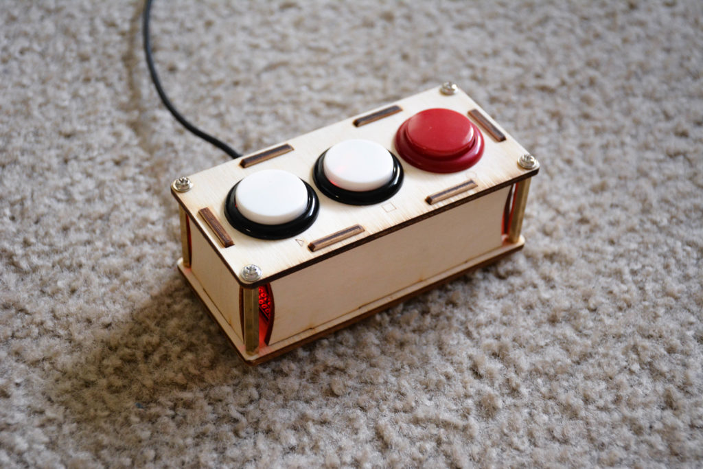
Transport-1-5 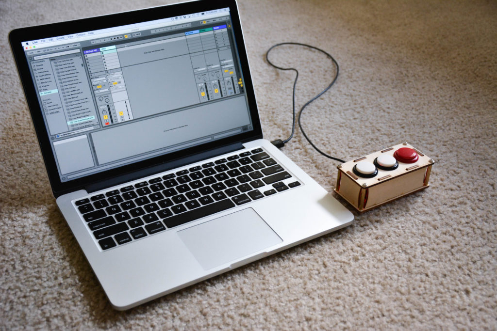
Transport-1-2 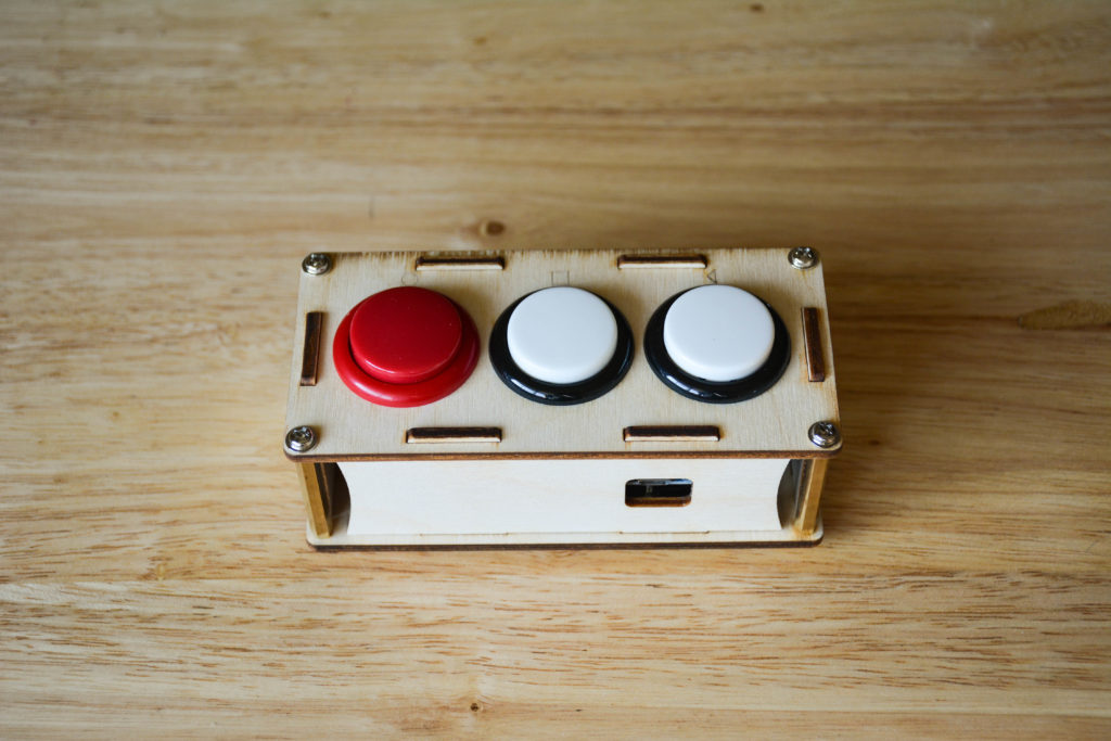
Transport-1-6
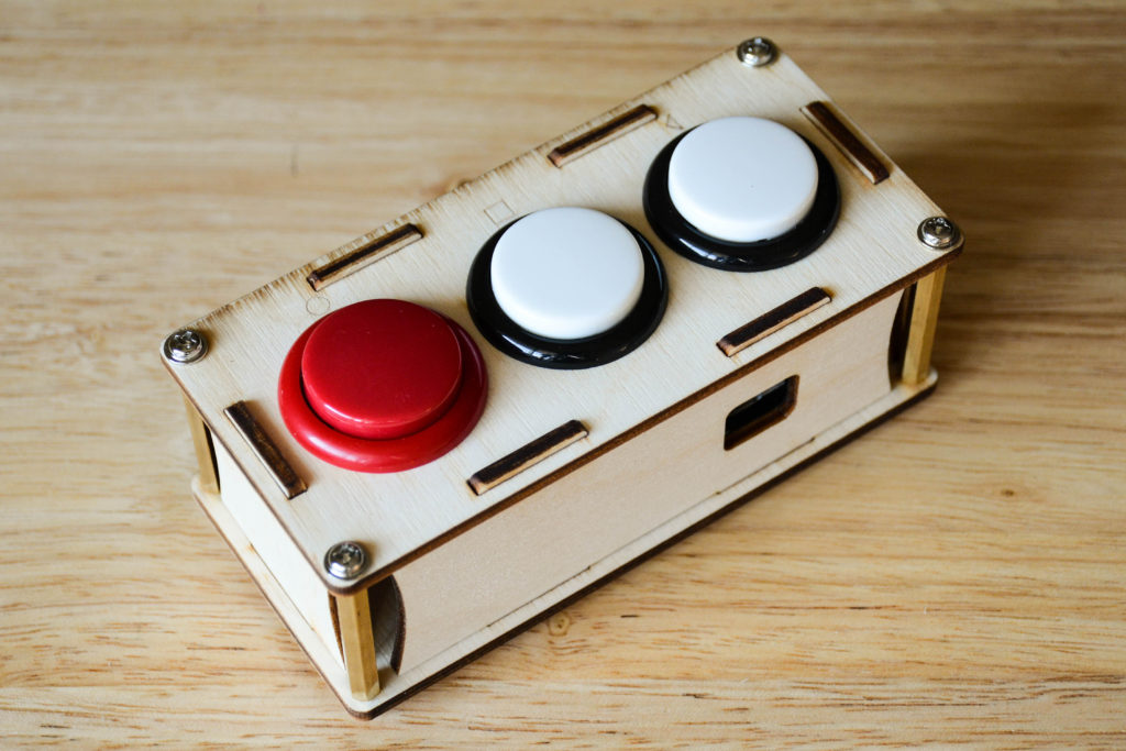
This small guy is great if you just want to have three buttons in your workflow, like play, stop and record, or if you just want to start learning how to build a MIDI controller, without having to commit to a bigger project.
The Transport, how a I call it, was made as a custom made controller for a client. But, as I posted on my site, more people ended up wanting it, so I also started selling it in our store.
But, what can be better than buying? Building your own! That’s why I decided to put this tutorial, so you can build your own “The Transport”!
Here is a review of the Transport as a regular MIDI controller:
And as a controller for Pro Tools (yes, they are different):
But, let’s get to work!
Materials needed:
- 1x Arduino Pro Micro with headers
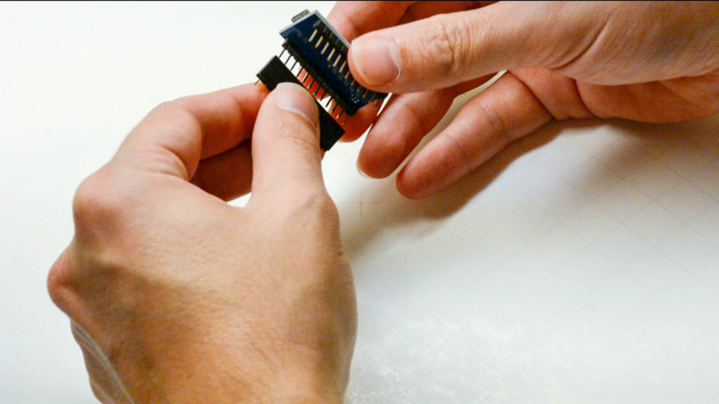
- 2x 12 pin male-female headers
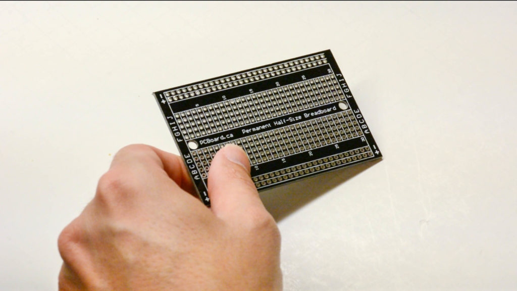
- 1x Solderable breadboard
- 3x arcade buttons 30mm (Sanwa style)
- 4x M3 35mm male-female hex spacers
- 1x M3 10mm screw
- 4x M3 1/4″ screws
- 5x M3 3mm nuts
- Wires
Intro
Buying components sometimes can be an overwhelming and tedious task, due to the gigantic amount of variations for each thing. So, I pointed to the exact components that I use. But, if you wanna buy in your local hardware store, or if you have them at home, it’s totally up to you.
The most important part of this project is its brain. The brain of our controller is going to be an Arduino Pro Micro. Arduinos are great for doing from robots to MIDI controllers, and if you follow this page, you know that we love them.
If you are new to Arduino, make sure to watch our free course, the DIY MIDI Controller Workshop.
If you are wondering “I already have an Arduino Uno (or any other model), can I use it?”, the answer is, “it depends, but mostly no”. The Arduino Pro Micro is in the family of the Arduinos that can be transformed into a MIDI class compliant device, and also can send keystrokes, which will be needed if you want to use it with pro tools.
This is an easy project, the only catch is that you’ll need to saw the solderable pcb in order to fit it in the enclosure.
Steps
First of all: download the files on the Github repository.
1 The enclosure
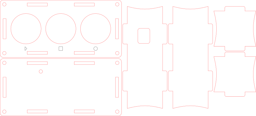
Enclosure is that thing you can make however you want, and improvise however you want. But, of course I wouldn’t let you down on it. I made available all the parts that I’ve designed for laser cutting and you just downloaded it.
The material you need to cut needs to have a 3mm width. I used plywood, which I think looks really good, but you could use acrylic, for example. If you don’t have a laser cutter available, you can mail me and I can cut one for you.
The red lines are for cutting and the blacks are for engraving.
2 The circuit
Now, it’s time for soldering! And for that you should follow the schematic you’ve just downloaded.
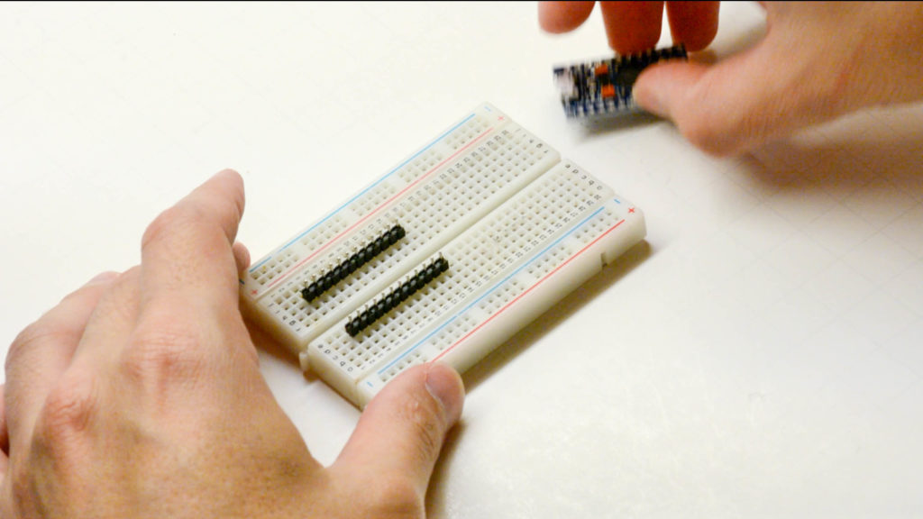
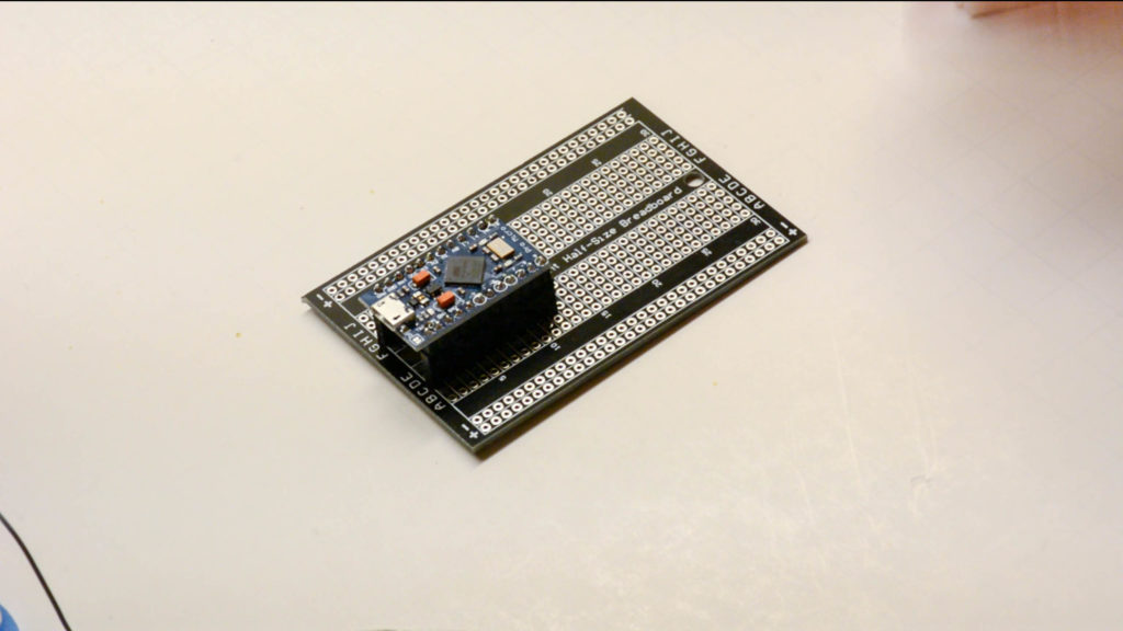
2.1 Solder the Arduino to the male-male pin headers
You should solder your pin headers into the Arduino. I use a breadboard for that, it helps a lot.
Arduino Pro Micro 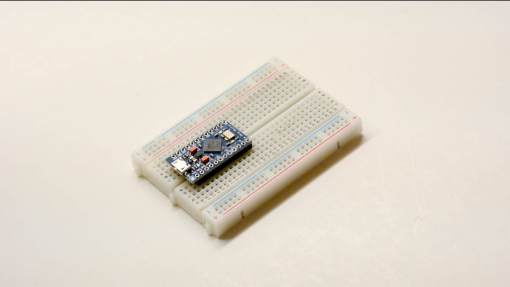
Arduino Pro Micro 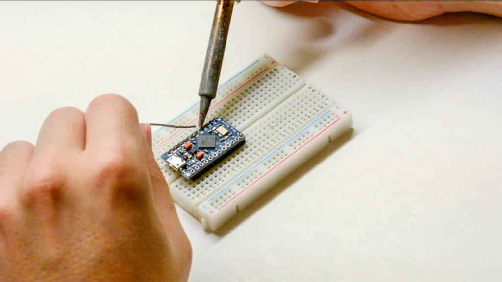
Arduino Pro Micro 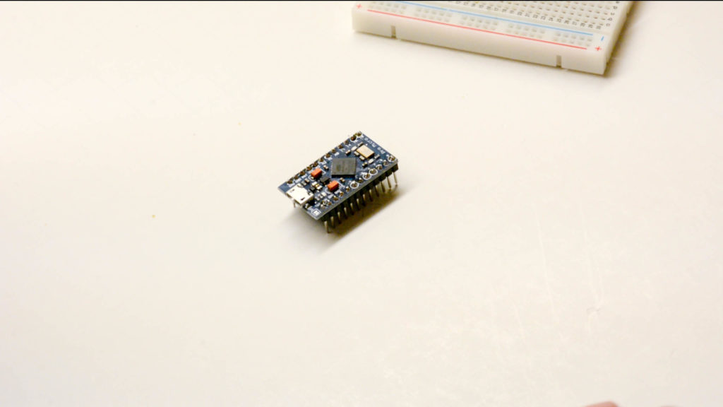
2.2 Solder the male-female headers into the solderable breadboard
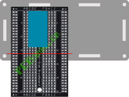
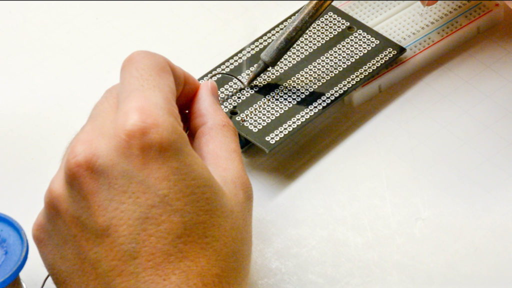
Before doing that you should cut the solderable breadboard in order to fit in the enclosure. You should cut about the red line, so the pcb fits tight inside the enclosure. The length of the part that stays inside the controller is exact 47.8mm. Just do your best, it doesn’t need to be perfect!
Now, it’s time for the soldering.
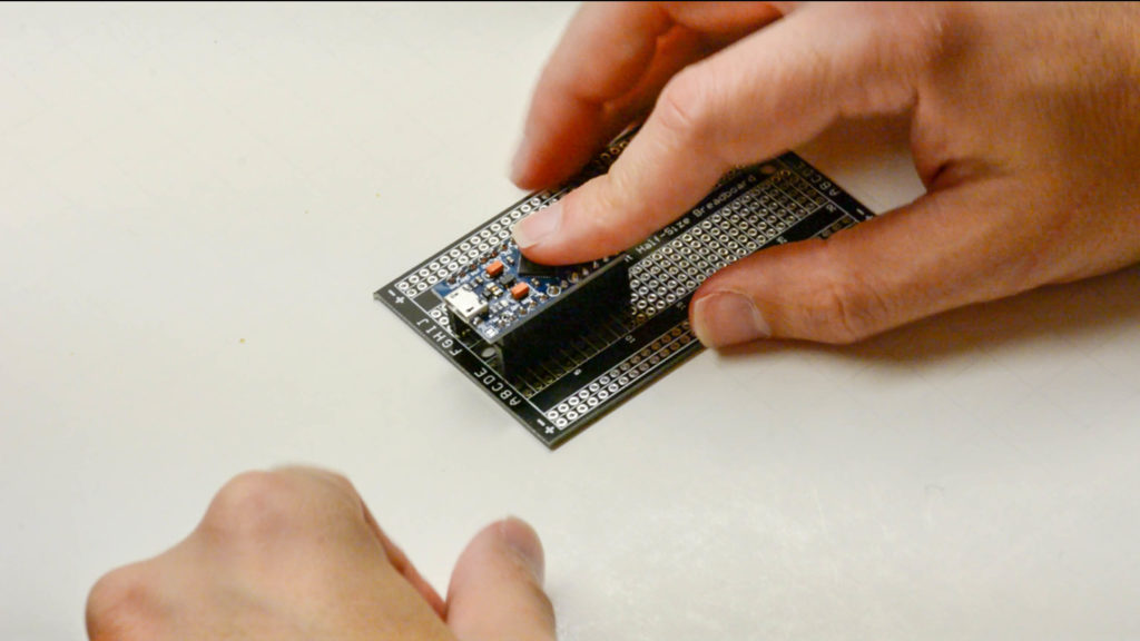
- Connect the male-female headers into the headers of the Arduino.
- Snap in the solderable breadboard.
- Solder.
Be careful to put the board in the exact same place as in the schematic! It will be a little bit to the left, because it can’t fit in the middle. This is important because of the layout of the enclosure.
2.3 Connecting the arcade button to the breadboard
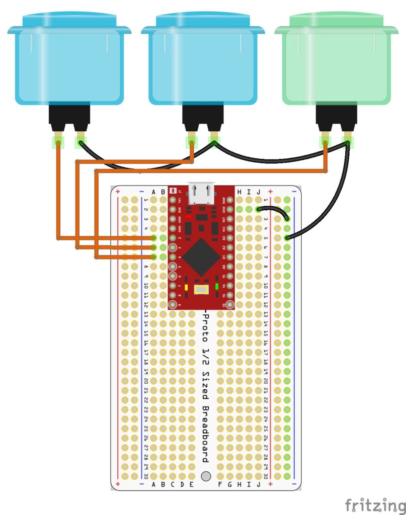
- Cut 3 colored wires with about 15-20cm.
- Cut 3 5cm (preferred black) wires
- Cut 1 15-20cm black wire.
- Strip all the tips of the wires.
- Snap the arcade buttons on the mounting holes on the top.
- Solder exactly how you are looking in the schematic. Use the long black wire to connect the last arcade button to the solderable breadboard.
3. Assemble the controller
- Disconnect the Arduino from the female headers.
- Screw the breadboard in the bottom part of the enclosure using the 10mm screw and nut.
- Put the Arduino back on its place.
- Put the spacers, with the male connector, in the bottom part of the enclosure and fasten them with the nuts.
- Snap all the enclosure parts. Be sure to leave the front part with the USB hole in the right place.
- Put the remaining screws in the spacers.
- Put some rubber feet!
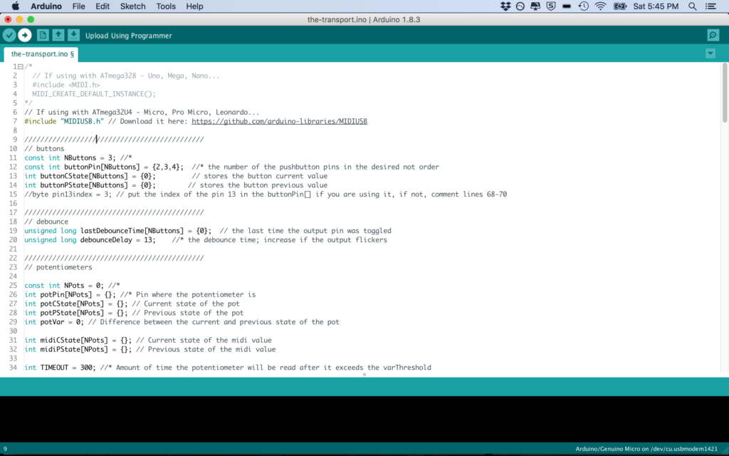
4. Program your Arduino
- Connect the Arduino to the USB port of your computer using a USB micro cable.
- Download and install the version 1.6.8 of the Arduino’s IDE.
- Open the code that you’ll use, regular MIDI controller, or for Pro Tools.
- Go to Sketch > include library > Manage Libraries.
- Search for “MIDIUSB”. Install the MIDIUSB Library. This library allows the Arduino Pro Micro to become a MIDI Class compliant device.
- Go to Tools > Port and chose your USB port.
- Go to Tools > Board and choose Arduino/Genuino Micro.
- Upload the code clicking in the arrow on the top left corner.
Be happy! (or not)
Now your controller is ready to shine every where you go!
If something went wrong along the way, try doing a couple things:
- Restart your computer.
- Make sure you installed the right library.
- And make sure that you have a good quality usb cable. This is really important! I’ve already seen many crapy cables, like those smartphone ones, that don’t work with the Arduino, so be sure to buy a good one.
So, how was your experience building this little guy? Have doubts? Let me know in the comments bellow!
Feel that you want to learn more?
Be sure to watch my free course the DIY MIDIController Workshop.
And my complete uber duper course Making Music with Arduino.
If you liked it, please share with your nerd friends! See you!