Fliper
DJ

Fliper DJ

Build this MIDI controller using an Arduino: Fliper Dj

In this tutorial, I’ll show you how you can build this awesome MIDI controller! The Fliper DJ is a MIDI controller which is based in the Arduino platform. It contains 16 arcade buttons, 7 rotary potentiometers and 3 slider potentiometers. One of the potentiometers allows you to change the midi channel of the buttons, making it possible to have four banks of buttons, 16×4. The Fliper DJ is a USB-Midi class compliant device, no drivers or converters needed!

First of all

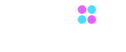
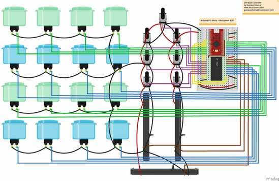
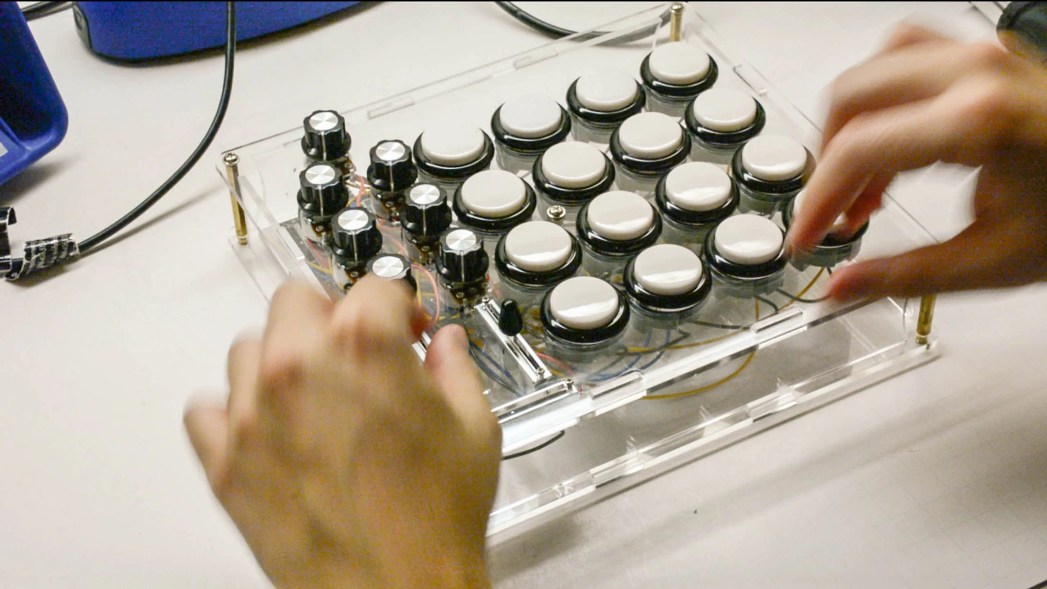
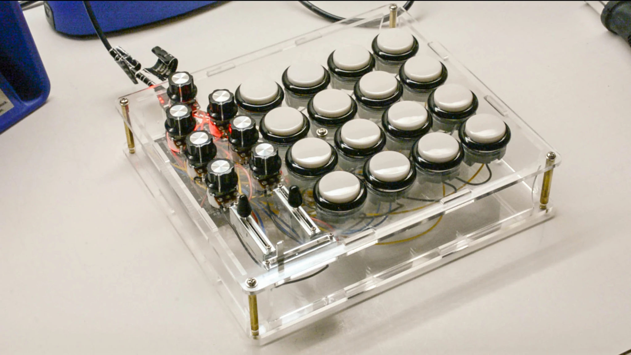
My idea when I designed this guy was to have a controller that was great to trigger samples, launch clips, etc, but also was good to control a simples mixer, with two channels, containing volumes, crossfader, lows, mids and highs. I also like the idea of having different banks for the buttons, so I programmed one potentiometer, the one in the top, to select between for banks. Although I designed thinking in a mixer, you can map it however you want it. I think that the enclosure ended up quite nice too! And a great thing is that, using the Arduino Pro Micro, it can be a true USB-MIDI device.


Before you start, know that you’ll need some experience with soldering, and you should know how to use a multimeter to troubleshoot. I highly recommend you that you watch my free course the DIY MIDI Controller Workshop, where I teach the basics about the components, Arduinos, and how to use the Arduino IDE (the software we use to program our Arduino. And take a look also at our complete course, the Making Music with Arduino, the course where I teach about everything I know about making MIDI controllers, teaching you how to program, about all the electronics stuff and much more!


Here you can see it on Ableton Live!

Here you can see it on Ableton Live!

Materials

If you don’t feel like you want to look for all different parts, you can buy the whole kit here in our store. Doing that, you also help (a lot) our channel, helping me making new tutorials like this!

Downloads

Before you start, download the files with the code, schematic and design for laser cutting.

You should follow
these schematics:

Something really important: All the components are placed like you were seeing them upside down, with the exception of the breadboard. Wire your breadboard normally, but keep in mind that all the rest is upside-down. For example, your rotary potentiometers are upside down, so you should put the red wires in the left! Pay attention to the pictures.

That being said, watch this cool video about the creation process, and let’s get started!

1 The board

The first thing we’ll do is preparing the board. For this part we’ll need the Arduino Pro Micro, the solderable PCB and the multiplexer cd4067 and jumpers.

I found that the best way, for me, was using a solderable breadboard. A solderable breadboard is a pcb that comes configured exactly like a breadboard, but you can solder on it!

I chose the Arduino Pro Micro, because, as the Arduino Micro and Leonardo, it comes with the ATmega32U4 uC, which can be transformed into a real USB-Midi class compliant device. So, no other softwares or drivers are needed.

The cd4067 is an analog multiplexer, which means that we can multiplex the number of analog inputs in the Arduino. This way, we have all the inputs we need for this project.

1.1 Solder the Arduino to the male-male pin headers

You should solder your pin headers into the Arduino. I use a breadboard for that, it helps a lot.

1.2 Solder male-female headers into the solderable breadboard

1. Connect the male-female headers into the headers of the Arduino.
2. Snap in the solderable breadboard.
3. Solder.

Be careful to put the board in the exact same place as in the schematic! It will be a little bit to the left, because it can’t fit in the middle. This is important because of the layout of the enclosure.

1.3 Solder the cd4067

Pay attention that the cd4067 has a semi-circle in one side, this should be facing the Arduino.

1.4 Connect the jumpers

Try using red for 5v, black for GND and other colors for the other pins. I just had red and black, so that was it.

2 Rotary potentiometers

2.1 Solder the wires to the rotary potentiometers

I prefer doing this before connecting them to the enclosure. You might want to do differently, but that is what works best for me. I usually do all the reds, then blacks, and the middle ones with colors. After that, trim that part, which is just going to bother us, like I do in the last pic.
In the end, don’t forget to use a multimeter to check the continuity of the black and red wires.

2.2 Connect the potentiometers to the top of the enclosure

Before connecting anything to the enclosure, don’t forget to take off the plastic peel from the acrylic. Connect all the potentiometers and tight them with pliers.

3 Slider potentiometers

Connect your potentiometers, with the terminal 1 facing upwards, or left (looking upside down), and screw them in place. After that, solder their wires, like the schematic.

4 Buttons

4.1 Connecting the buttons

Now it’s time to snap our arcade buttons into place. One thing that I noticed is that those black buttons are a little bit harder to fit into the holes then the colored ones. Sometimes it felt that I could break the acrylic, so be really careful! Try to make them all aligned, it’s more beautiful and it will be easier to solder the wires.

4.2 Soldering the wires

With the black jumpers solder all the common ground pins. They are called common ground because they are all sharing the same gnd. What I advise you doing is putting two wires in one terminal of the button, facing opposite sides, then solder them. With a multimeter, check the continuity of the gnd. Then, solder all the other wires.

5 Soldering all the wires to the solderable breadboard

Now things start to get really hairy! It’s really easy to make a mistake, so all the attention is needed! This time, I really like to see the schematic on Fritzing, because it allows me to select the wire and see where it’s going.
Maybe, now it’s a good time to test your controller, so you can jump to the step number 7 and upload the code.

6 Mounting the controller

For this project I designed an enclosure that I really liked. It looks good and is really sturdy. You can use acrylic, or any type of wood, it just needs to have a width of 3mm. You can laser cut the files that you’ve downloaded, or you can buy the kit, or just the enclosure from our page! And doing that you support our page. Tada!

6.1 Mounting the pcb

Now, it’s time to put everything in place! First thing is connecting the pcb into place. For that, you need, first, to remove the Arduino. Then, you can use two 3mm screws to tight the pcb. After you’ve done that, you can put the Arduino back on its place.

6.2 Mount the spacers

Connect the five spacers into the bottom, using the male part.

6.3 Put everything together

Now, put all the parts of the enclosure together. The only thing we need to pay attention is that the front part, the one facing the audience, has the hole for the USB cable. It needs to be facing the Arduino (obvious), but you also need to choose the side that makes the hole stay near to the bottom, so the USB cable can reach the Arduino easily. Hard to explain, but you can figure out. Then, screw the spacers with the 3mm screws.

6.4 Put the knobs into place

I’m using potentiometers that are not knurled, those ones that you can use those Boss style knobs. To tight the knobs you’ll need a tiny screw driver.

6.5 Put some rubber feet!

I’m using potentiometers that are not knurled, those ones that you can use those Boss style knobs. To tight the knobs you’ll need a tiny screw driver.

7 Program your Arduino

For using the Arduino Micro as a true USB-MIDI class compliant device we’ll need to do some things first.

7.1 Download the necessary libraries

The Arduino Micro can be recognized as a USB device, such as a mouse or keyboard, natively, but not as a MIDI-USB device. But, installing the MIDI-USB library, this is possible.
In this code I have implemented the concept of “threads”, which allows the Arduino to perform different tasks at the same time. This is not a real thread, but it lets you run the code faster, decreasing latency.
For using all the inputs in the Arduino I used the multiplexer cd4067. In order to use it, I’m using this nice library:

7.2 Install the right Arduino's IDE

The IDE (Integrated Development Environment) is the environment that you use to upload the codes in Arduino. The USB-MIDI Library only works on some versions, such as version: 1.6.6; 1.6.8; 1.6.4 and 1.6.1. I installed 1.6.8 and it worked fine.

7.3 Upload the code

  1. With a micro usb cable, connect your Arduino to the computer.

  2. Open the Arduino’s IDE.

  3. Open the code that you downloaded.

  4. Go to tools > board and select Arduino Micro.

  5. Go to tools > port and select cu.usbmodem, or tty.usbmodem (Mac), or COM4 (Windows). 

  6. Upload the code, click in the right arrow, in the upper left corner.

8 Make some noise!

You can use it in any DAW, but before I use it in a DAW, I like to use the software MIDI Monitor, to monitor everything that is coming from the MIDI controller. Now, your MIDI controller should show up as Arduino Micro. As soon as I can, I will post a tutorial showing how you can change its name.

9 Troubleshooting

At this time, or you are crying of happiness, or sadness, because you controller didn’t work. There are several things that can go wrong, and most of them are simply because of lack of attention. You could have soldered a wire in the wrong place, or even forgot one, so let’s see which are the main problems:

9.1 Your code doesn't compile

  • If it doesn’t compile, or it takes forever, try changing the port, from tty.usbmodem, to cu.usbmodem.

  • Make sure that you installed the right Arduino’s IDE and installed the USB-MIDI and Threads libraries correctly.

  • Take your USB cable off and put again.

9.2 Components not working

  • if you have just one button that’s not working, or just one potentiometer not working, probably it’s not well soldered in the pcb,  it’s in the wrong place, or it’s a bad component.

  • If you have several components not working, like all the buttons from the 10th to the last one, the reason is probably because one of the common ground connections is bad. Use the multimeter to find the problem.

10 Conclusion

I really hope you enjoyed this tutorial and I’m really looking forward to see the controller you are going to build! Don’t hesitate to post videos, pictures and any doubts in the comments below!

If you think that this controller is a little bit hardcore for you, I totally advise you to start with our free course, the DIY MIDI controller Workshop, where I start with a simpler prototype.

And if you want to get deeper and really learn how to create your own codes, or to understand how I create mine; how to design enclosures, and much more; check our complete course, the Making Music with Arduino!

That’s it guys, see you in the comments bellow!