
Hello, my Nerd Musician friend! I think if there’s one thing every nerd musician would like to have is a Theremin, right? Look how wonderful, Theremin himself playing Theremin!
Since buying one can be out of the question for many people, there are several ways to do the same things yourself. The Theremin has two antennas and a system that, frankly, I do not even know how it works, but using our friend Arduino, we can come up with similar things or adapt to what we want.
Me, for example, have already done some MIDI Theremins, the Theremidi, where I sell through the Bit Controllers. Take a look!
In that one I used infrared sensors and turned the MIDI signal so that scales are played! Anyway, this was a very long project and maybe I’ll make a tutorial here in the future. If you want to know more, visit Bit Controllers! www.bitcontrollers.com
But then, what do we have for today? A way to make a Theremin, very simple, fast and cheap! Here’s a little video of what I did:
So, let’s go to the materials!
– Arduino Uno
– Breadboard
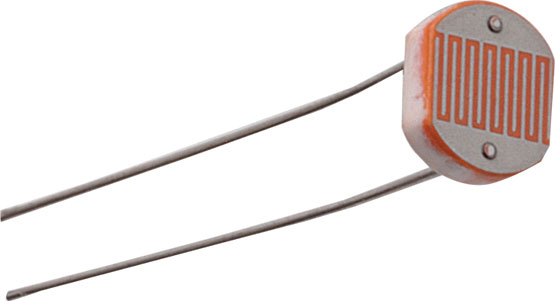
– LDR Photoresistor
– 10k Resistor
– A 4-ohm speaker or buzzer
– Jumpers
Our main component, which is the sensor we are going to use, is LDR. The LDR is a photoresistor, that is, it changes its resistance according to the light intensity.
And that difference in resistance is that we will measure and map in sound frequency, which will be emitted by our speaker.
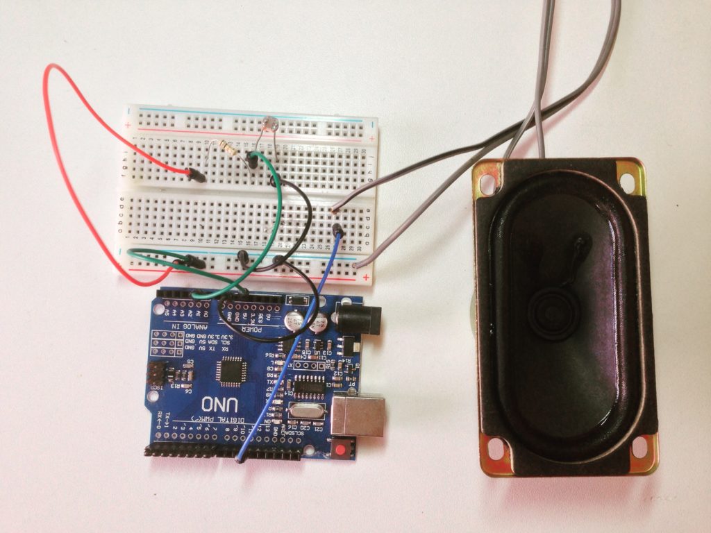
Circuit
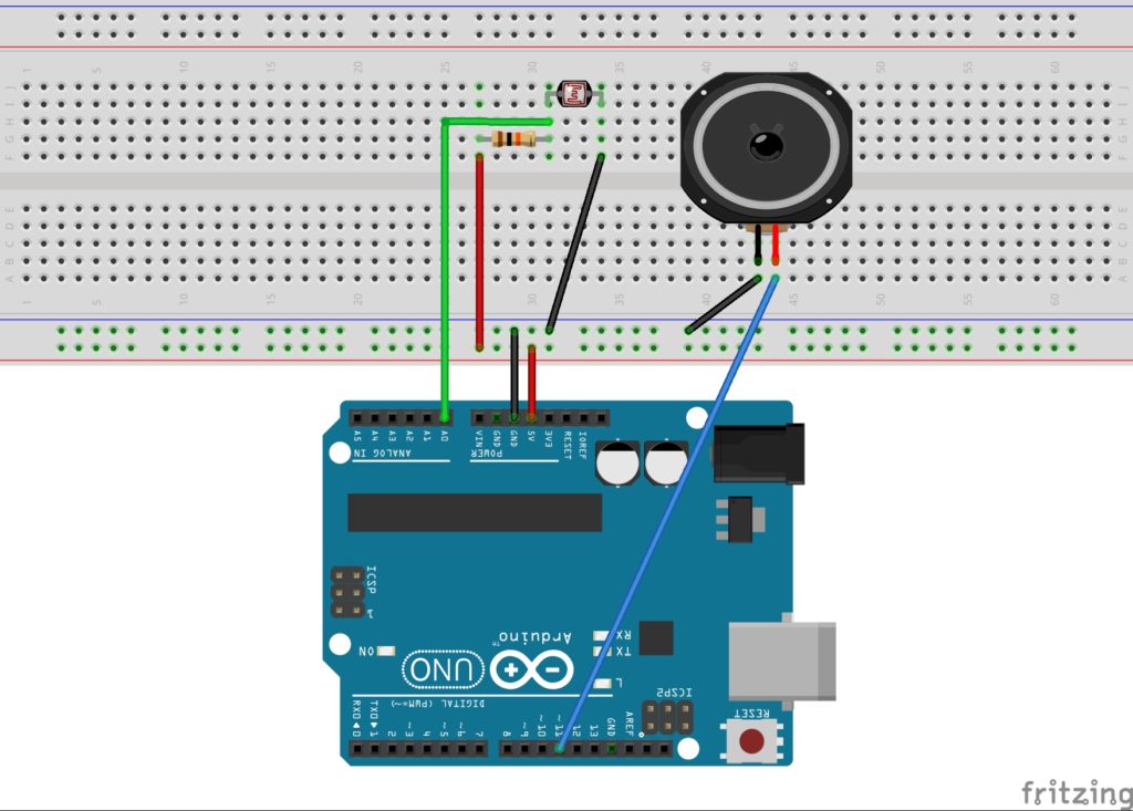
The LDR has two terminals, one will be connected to the GND and the other will be connected in two different places, in the 5v through a 10k resistor and in an analog port, in this case in the A0. The speaker has two terminals, the negative goes in the negative and the positive goes in a PWM digital port of the Arduino, in this case the 11. Attention, for the speaker to work it must be connected to a PWM port.
Code
Upload this code to your Arduino
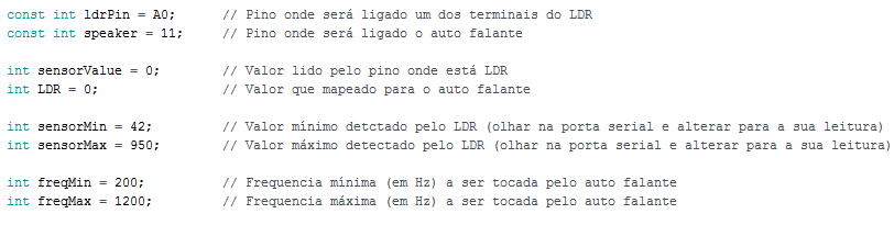
In the code you will need to adjust some things according to your preference. In the first two variables place the respective pin, as documented. To configure your sensor, after uploading the code, open the Arduino’s serial port and see the minimum and maximum values that appear as you block or or let light through the LDR. Set these values where indicated: sensorMin and sensorMax. In freqMin and freqMax, set the minimum and maximum frequencies that will be played by your Theremin, remembering that they are in Hertz, so the lower, the lower the note.
Have Fun!
Done! You can have fun, bother your neighbors or show off to your friends with your DIY Theremin! If you liked this tutorial you will probably like this series of videos where I teach how to make a MIDI controller with Arduino!
If you liked it or not, or have any questions, leave your comment below, I will greatly appreciate it!